What If CFD Modelling Was Readily Available For Residential Duct Design
September 13, 2019
 What If CFD Modelling Was Readily Available For Residential Duct Design?
Author: Sam Myers
Abstract
Within the confines of the HVAC field, airflow behavior is one aspect that can be difficult to understand when it comes to proper duct system design and airflow measurement. The challenge of providing a visual display of an issue that is invisible to the naked eye is a regularity we face when working with clients, apprentices and students. Once a duct system is installed, we can use diagnostic tools such as flow hoods and duct testers to measure and expose air flow and leakage, then record our reading. We can also use thermal imaging equipment and smoke generators to make air behaviors visible. However, these actions are more reactive than proactive. What if we could see how air is supposed to behave inside our duct system during the design phase? Or show what happens if mistakes are made? The use of computational fluid dynamics (CFD) modeling can allow contractors and designers to see airflow behavior in the design phase. With 3D modeling entering the HVAC design software market, it is now possible for CFD to be the next big step in the duct design process for both commercial and residential projects, allowing designers to quickly discover and repair flaws in their system designs. This paper will cover how CFD modeling can be applied to the HVAC and building performance industries and provide a real-world example of how these models look.
Keywords
Computational fluid dynamics, CFD, Airflow, Manual D, Duct design
1. Introduction
Designers and engineers in the building and HVAC industries have used Computational Fluid Dynamics (CFD) to model air flow behavior in duct systems and other assemblies for decades. However, it is seldom used in the residential industry mainly due to the high cost of the software. Until recently, residential HVAC design software lacked the ability to produce the 3D renderings needed to produce a CFD model.
The purpose of this paper is to present an example of how CFD modelling can assist in the duct design process in residential applications. Now that multiple options exist for creating realistic 3D drawings specifically for residential duct designs, it is possible to integrate CFD modelling to quickly and effectively locate possible flaws within systems before they are installed. Creating a CFD plug-in for duct design software and making it a regularity in the design process would be the next big step to help designers improve the quality of their work.
2. Merging HVAC Design Software with CFD Modeling
Over the years, various HVAC load calculation and design software options have been developed to help designers and contractors provide optimum system designs. This type of software provides users the ability to create efficient duct designs that deliver optimum efficiency and occupancy comfort. Before a user can design the duct system, the heating and or cooling load (Manual J) must be calculated. This requires users to enter various aspects of the home including construction inputs from the plans or details from an existing structure. These details include the framing width and spacing of exterior walls and ceiling/roof structures, insulation, fenestration, infiltration, etc. Some software manufacturers have provided the ability for users to draw the house in the software in a CAD-like fashion along with the ducts with all components involved. Specific equipment can also be selected from a list of manufacturers and models (Manual S). Designers can also account for building infiltration by entering a blower door number to make the load calculation even more accurate.
Some HVAC software developers are now producing software options that allow for 3D duct design. Some are using a CAD-based platform (such as Right-CAD) while others are using a video game platform (such as Kwik Model) to freely draw 3D ducts in real time. This provides designers and contractors the ability to present customers with a realistic view of how their duct system will appear and operate. This also helps installers by providing them with a clear picture of how the system should be installed in the field.
At this point, there are no residential HVAC design software developers integrating CFD modelling with their products at a reasonable cost. Currently, CFD software is an expensive tool to use. However, similar to other forms of technology introduced in the HVAC industry, costs may come down as technology advances. CFD and HVAC design software companies may also discover value in partnering together to make CFD more available to contractors and designers working with lower budget projects. This paper aims to introduce this concept to help improve the duct design process by using CFD to identify some common issues in duct systems.
3. Benefits of using CFD Modeling in Residential applications
3.1 Easily Expose Design Flaws
With its ability to show changes and differences in air flow velocity and laminarity, designers can use CFD modelling to quickly check behind themselves to see if a duct size, bend, or connection should be altered. For example, air flow velocity is represented by color. If most of the bedrooms of a house are of similar size, construction and exposure and one supply duct is a different color than the rest, that duct size may need to be reconsidered (as shown later in this paper). Turbulence in a stream of air can also be identified in the model by groups of smaller lines that represent air flow direction. This could be caused by inadequate duct connections such junction boxes, sharp bends in the duct, or obstructions in the air pathway. Having a visual representation of air flow turbulence can help the designer choose the right connections to maintain more laminar flow.
3.2 Training
Since air behavior is usually invisible to the naked eye, it can be challenging to present a visual aid to students who are learning duct design best practices. Having a visual aid to show air flow dynamics can help trainers show students what happens to the air when different connectors are used, bends are added, ducts are improperly sized, etc.
3.3 Locating Optimum Airflow Measurement Access Points
In some cases, airflow must be measured inside the duct using a manometer, pitot tube, anemometer, etc. This requires making a hole in a duct, trunk line or plenum and inserting a probe to take the measurement. A best practice for this is to take a measurement where there is the least amount of turbulence. Having a custom CFD model of the system can help identify the best place to access the duct system to take the measurement.
4. Project Discription
To determine how CFD modelling could assist in duct design in a real-world setting, an existing residential duct system was selected to determine if any possible design improvements could be suggested (if the system should ever need replacing). The subject duct system is installed in a single-family residential home in Raleigh, North Carolina. The ducts distribute conditioned air from a split heat pump installed in a traditional code-built home constructed in 2015.
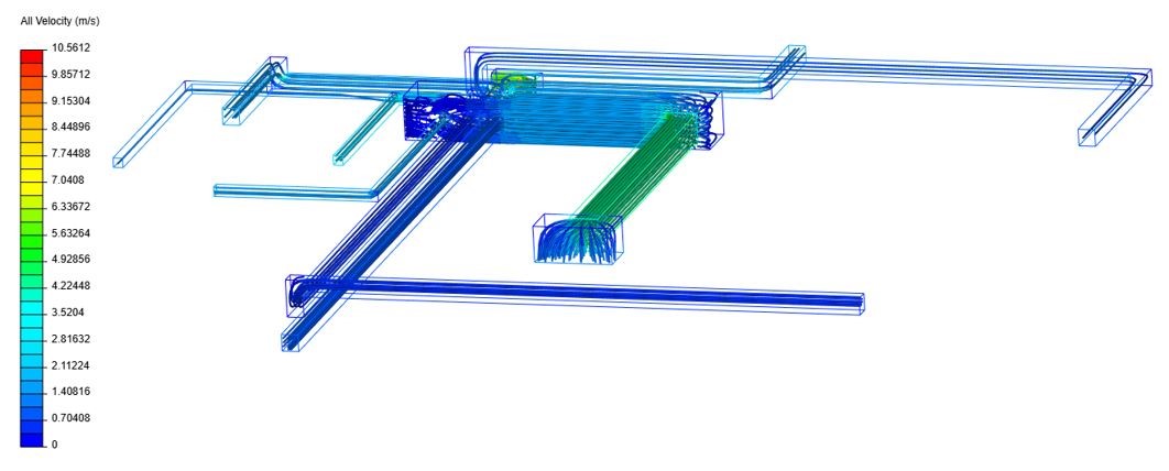
Raleigh, NC is in the south-eastern United States where duct systems are often located in the attic. Attics in this region are typically vented and unconditioned. The indoor coil and fan are typically attached to rigid sheet metal supply and return plenums that are then attached to the supply trunk and a return that pulls air from the main body of the house. Every component of the house and duct system was re-recreated in HVAC design software. The initial 2D drawing generated in the software can be seen in Figure 1.
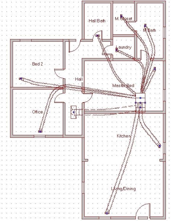
Figure 1: Subject house layout and duct design generated in HVAC design software
Once the layout was created in the HVAC design software, the next step was to create the 3D model. Depending on what software is used, a 2D layout may not be needed if plans are available. The 3D drawing used to create the CFD model can be seen in Figure 2. In this case, SketchUp was used to create the model since certain details in the supply side of the system could not duplicated in some of the other 3D HVAC drawing tools that were explored. However, those tools would only need some slight adjustments for them to be used for this example. In most other cases, those 3D HVAC drawing tools would be suitable.
Figure 2: Three-dimensional rendering of duct system
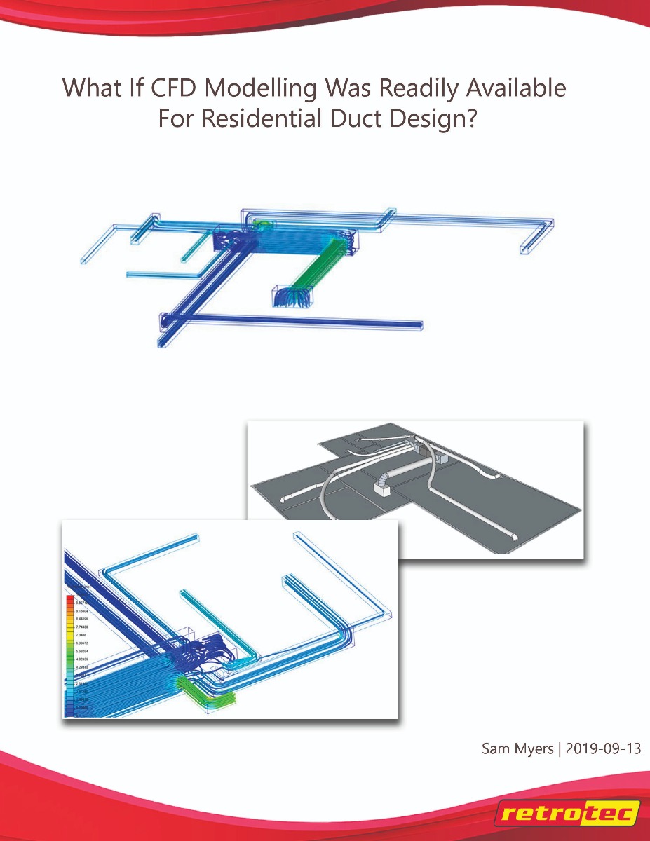
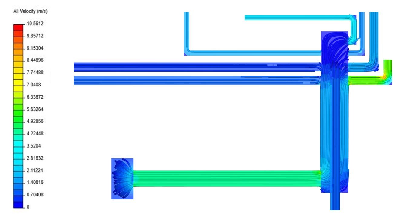
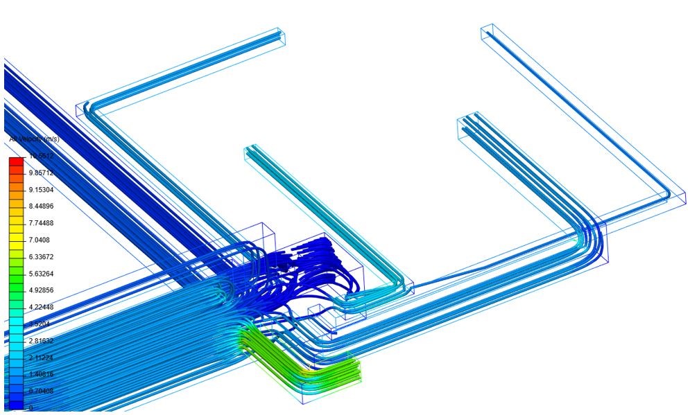
A 3D drawing will always be necessary to create a CFD model. Various CFD modelling software manufacturers allow users to import drawings and renderings of various file types to use with their software. Figures 3, 4 and 5 show the CFD model with different colors that represent air flow velocity. Refer to the key on the left side of each figure to see velocity.
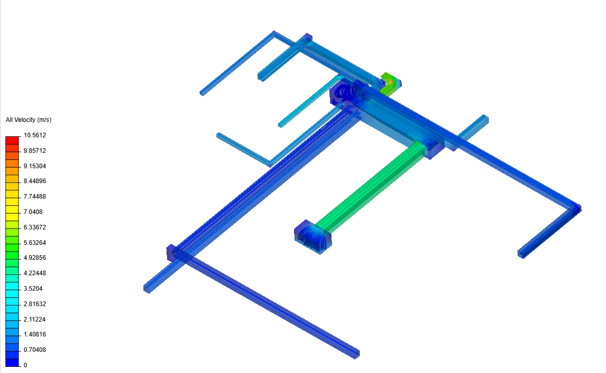
Figure 3: CFD model of duct system showing air flow velocity
Figure 4: CFD model showing velocity and turbulence
Figure 5: Bird’s eye view of duct system
Based on the CFD model, there is one issue that is immediately visible with the supply duct that serves the master bedroom. A closer look at the master bedroom supply duct (Figure 6) shows a short duct run with a 7-inch diameter. This will discharge approximately 348 CFM of air into the room, where the total airflow of the system is 644 CFM. This means more than half of the system’s airflow is being supplied into one bedroom. Based on the load calculation for this system, the master bedroom should receive approximately 90 CFM of air. This suggests a duct with a smaller diameter and a longer run should be used instead. Leaving the duct at its current length and reducing the diameter to 4 inches reduces the flow to approximately 150 CFM. In the installation, the installer used a hand damper to choke the airflow in order to avoid comfort issues, which has its own implications when considering efficiency. Adding hand dampers on duct runs is a good practice to control airflow. However, they should not be used in an attempt to correct improper duct sizing.
Figure 6: Short and oversized duct to master bedroom
5. CFD Limitations in Duct Designs
As helpful as it is in the duct design process, CFD modelling cannot account for all activity inside a duct system. One aspect that cannot be captured is the system’s installation quality. The CFD model assumes the system will be installed exactly as designed. The quality of the installation job will vary among contractors. For example, crimped ducts can be an issue in tight attic spaces when installing flex ducts. Some contractors may neglect measures to avoid this issue. Flex ducts are sometimes suspended from rafters or floor joists which can cause them to sag between the straps, thus reducing the velocity of the air flow. The amount of sagging between straps can vary depending on the installer.
In addition, some of the foldable tabs on connectors and collars might also be left in the air pathway thus disturbing the flow. It is also difficult to account for all the pressure drops throughout the system. This includes filters, coils and dampers. Duct leakage is also difficult to capture in the CFD model. If the installed duct system is significantly leaky, this will impact the air flow in the system.
6 Conclusion
As can be seen from the example presented in this paper, CFD modelling would be a powerful assistant for duct designers if it were readily available for lower budget projects. Currently, most users of CFD software include engineering firms, equipment manufacturers, research laboratories, and consulting agencies. Again, the main reason duct designers and contractors are not using this daily is due to the high cost of the software. However, the software that is currently being used for residential and light commercial duct design continues to evolve to make more accurate and realistic designs.
Some adjustments will need to be made to the current 3D duct design software programs that are currently available to produce a more accurate CFD model. Each software option has its own strengths and weaknesses. For this paper, several options were investigated and tried before one was selected. The issues found in some of these software programs could be easily addressed to accommodate CFD for most scenarios. It would also be helpful to include other aspects of the duct system that affect flow including the coil, filters, and any dampers installed.
7 Acknowledgements
The author would like to give a special thanks to Mr. Michael J. Housh for helping with the initial 3D rendering used in this paper. Mr. Housh is a highly skilled HVAC contractor located in Ohio, USA and contributes a great deal of educational information to the HVAC trade in North America.
The author would also like to acknowledge the work of Mr. Danil Solovey. He assisted by working as a consultant to help produce the CFD renderings used for this paper. Mr. Solovey is an equipment design engineer at Retrotec where he uses CFD modelling software to help improve on diagnostic tool designs.
Recent Posts