How to Build a Training Lab for Airtightness Testing
October 28, 2022
By: Sam Myers, Retrotec
If you are a trainer or educator in the building science field, having a visual aid to demonstrate scenarios that occur in real buildings is the next best thing to teaching on a job site. Air leakage in buildings can be a complicated topic to cover. To present the material in an effective manner, it’s helpful to have a volume of space, or a mockup, where you can manipulate building pressures, temperature, leakage, and hole sizes that connect multiple zones. This provides the ability to show students the physical principles that drive pressure change inside the envelope. A mockup also allows trainers to demonstrate how buildings can be tested and investigated with blower doors, duct testers, high-resolution manometers, thermal imagers, and smoke generators.
Feel free to use this guide to build your own mockup. Obviously, it doesn’t have to be an exact match, but you can use this as inspiration and make any adjustments to fit your needs.
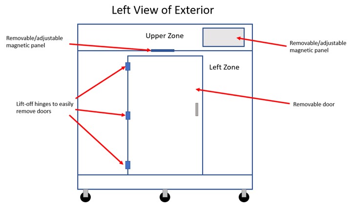
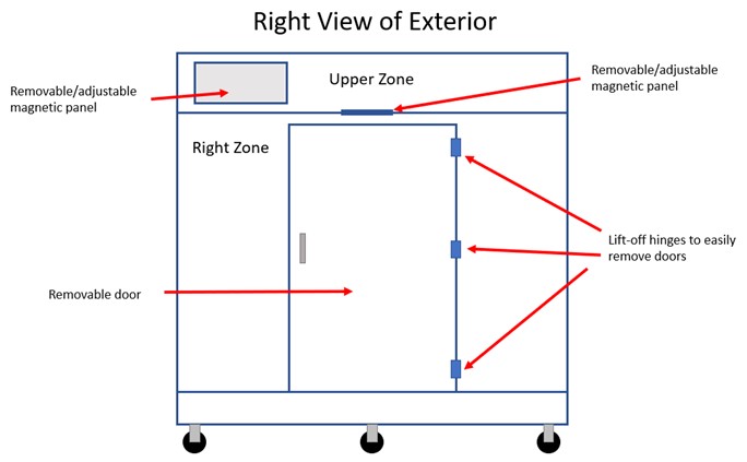
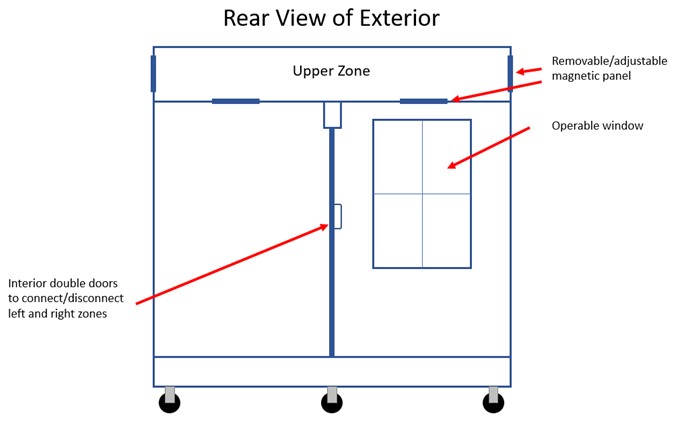
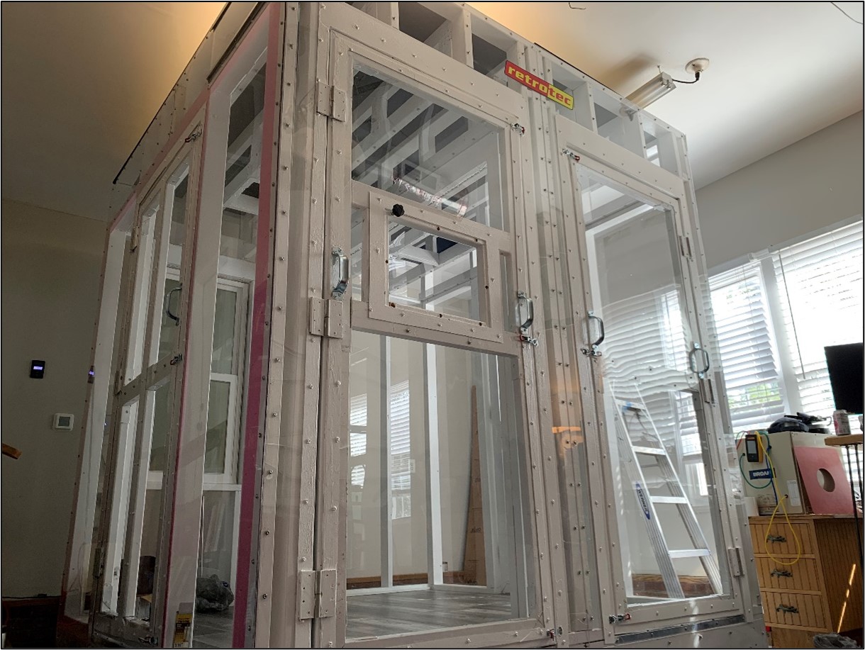
When I began planning my mockup, I wanted something with an 8’ by 8’ footprint on wheels that I could move around my workshop. I also wanted the ability to simulate leakage and air tightness tests for a variety of scenarios that we see in single-family, multi-family, and commercial buildings. The final product has one large zone that can be separated with a set of double doors installed in the middle of the interior. Closing these doors allows the mockup to behave like a duplex, or two apartment units that are side-by-side. There is also a zone above that can serve as an attic or duct system. There are two magnetic panels that can be removed or adjusted between the upper and lower zones. There are two more of these panels on the upper zone that connect the upper zone to the outside. These panels can simulate duct leakage to the outside or create a vented attic when open, or an encapsulated attic when closed. I placed a similar magnetic panel on one of the front doors to allow me to adjust leakage in the main zone. There is also an operable window on the back. Below are sectional drawings of the exterior of each side to give you an idea of how everything is arranged.
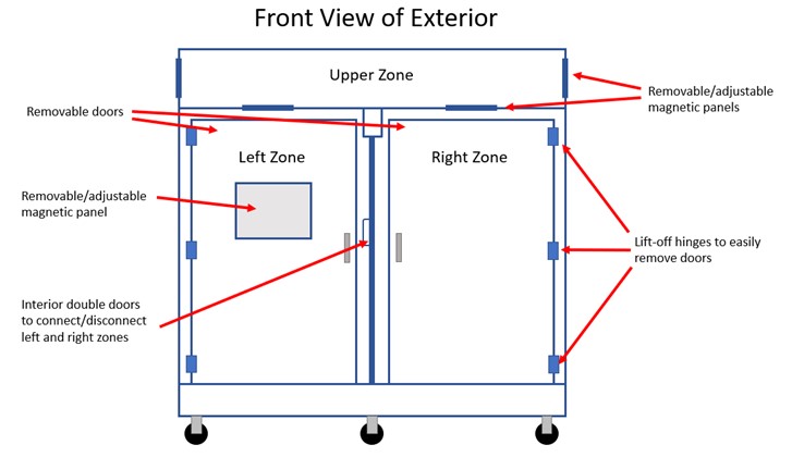
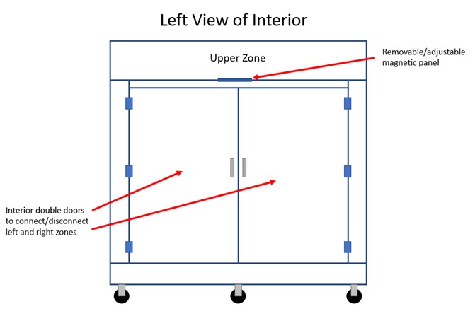
Below is a diagram of the interior of the left side that shows the double interior doors. When the doors are open, you can demonstrate air tightness tests of large buildings or single-family homes. When the doors are closed, you can demonstrate guarded blower door tests or multi-zone tests.
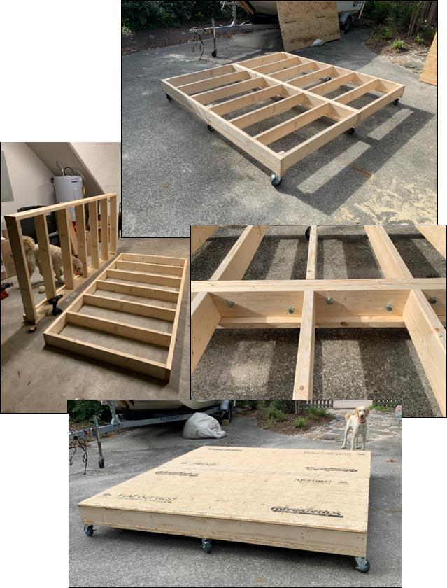
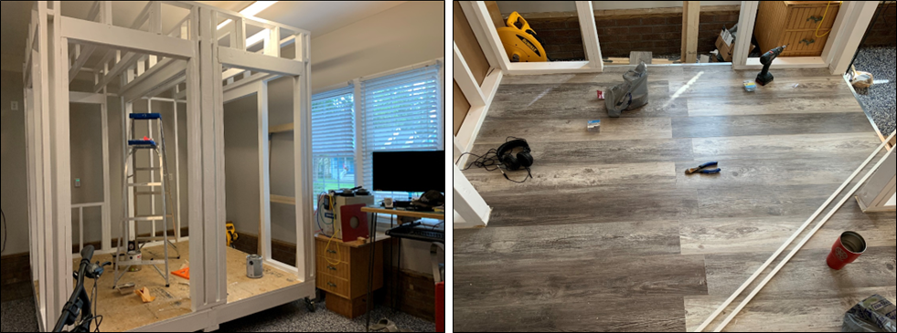
I originally wanted to make this mockup so I could easily disassemble and transport it if needed (however that idea was tossed aside once wall construction started), so I made two 4’x8’ floor systems that are bolted together. The floor joists are 2x6 boards. Once the floor system was assembled, nine caster wheels were installed. Each wheel is rated to hold 300 lbs. Two 4’x8’ sheets of subflooring were then installed on top of the floor joists. If you are planning to keep your mock-up in one place, there is no need to build the floor assembly in two separate sections. You can build one 8’x’8 assembly instead.
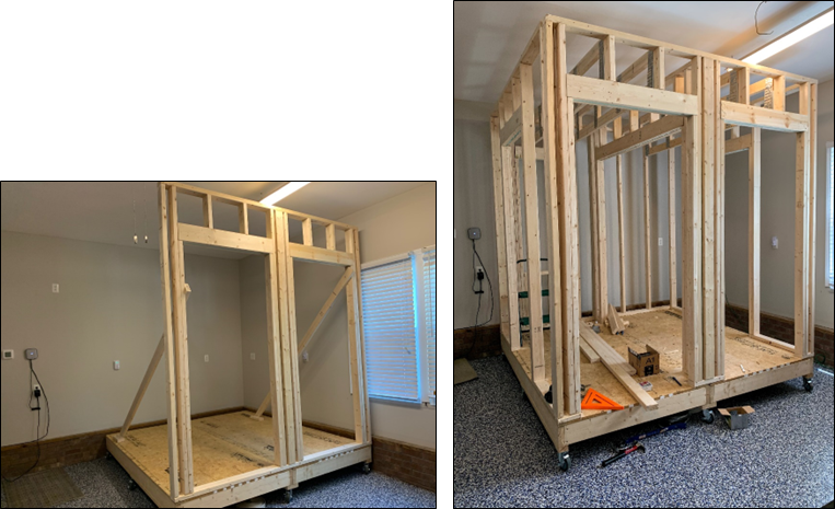
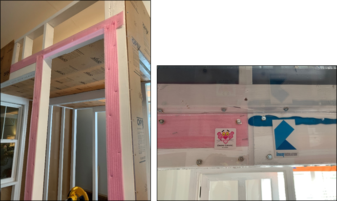
The walls of the mockup are stick-built, similar to what we see in residential construction with 2x4 studs. Advanced framing concepts were used where possible, including two-stud corners and insulated headers above windows and doors.
The roof trusses were stick-built using 2x4s connected with mending plates to make a dropped ceiling. This allows for an open assembly to create the upper zone. The bottom of the trusses need to be low enough to make room for a removeable panel on the exterior side to connect the zone to the outside. The bottom of the trusses also need to be a little bit higher than the interior and exterior doorways so the ceiling can be sealed to the headers. The trusses were installed using joist hangers. Once the trusses are installed, a plywood or OSB roof can be installed at the top. I painted the bottom of the roof a dark color so smoke/fog could be easily seen against it to make air currents more visible.
Once everything was framed, I painted each framing member white to give it a more finished look. I also installed flooring over the subfloor. These items are not necessary, but I chose to do this since it would be used in training videos to give it a more polished appearance.
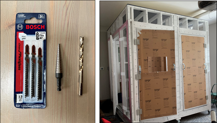
Each of the four doors were custom framed so they could be covered with clear acrylic paneling. I used a variety of air sealing materials such as foam gasketing and fluid applied sealants. I chose to use different products to show students how some leaks can be sealed in a variety of ways. The use of clear panels also shows how some air sealing materials compress once wall coverings are installed on top of them.
The wall paneling is ¼” clear acrylic. One-inch No. 8 sheet metal screws with a washer were used every six inches to fasten the acrylic to the framing members. This is likely overkill, but I wanted to be certain the acrylic would stay intact during high pressure tests with commercial grade fans. The dropped ceiling and the removable panels are also made of acrylic. The clear wall and ceiling panels allow students to see everything that’s happening inside the chamber during a test. It also shows how fog emitters can be used to locate leaks in building envelopes by making air currents visible. I used 4’x10’ sheets of acrylic for the walls to cover from the top of the chamber down to the bottom of the band joists on the floor assembly. Eight-foot panels would work fine, and they are less expensive and easier to source. For eight-foot panels, additional cutting and sealing will likely need to be done if your total wall height exceeds 8’.
When working with acrylic, be sure to use blades and bits made to cut and drill through acrylic/plexiglass. I used a jigsaw to make each necessary cut in the acrylic panels. A step bit was the best option for pre-drilling holes, but I needed an additional ¼” bit to drill holes after the panels were installed. The ¼” bit is made specifically for acrylic and plexiglass. Be sure to work slowly and carefully with the acrylic as it can easily crack when you are making cuts and drilling holes. The acrylic sheets come with an adhesive backing on both sides. You can mark on it with a sharpie or you can use a chalk line to mark your line to make cuts.
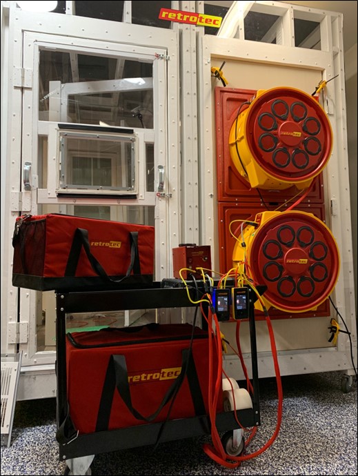
Once you have completed construction, you can use the simulator in a variety of ways. To demonstrate how you can see leaks with a thermal camera, a space heater works well to create a large enough ΔT to make leaks visible. You can also insulate part of the simulator with rigid foam board to show the difference between thermal bridging and air leakage on camera. A DucTester flange can also be attached to the top chamber to demonstrate a total duct leakage test, or along with a blower door installed in one of the main chambers below to do a leakage to outside test. Multi-fan tests can also be demonstrated by installing 2 fans set to lower ranges.
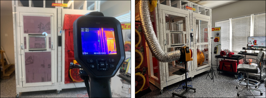
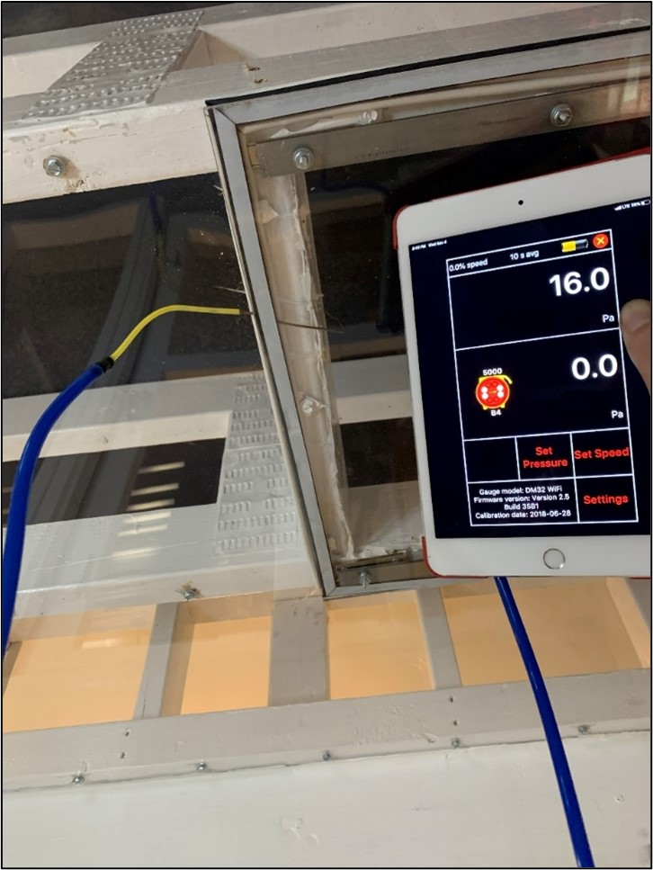
When a blower door is in use, you can use a second DM32 to demonstrate zonal pressure diagnostics (ZPD) on the top chamber. You can adjust the leakage in the top chamber to the outside as well as to the main space below to help explain the readings you get and how the ZPD reading is a ratio between zonal leakage to the outside and to the main body.
Hopefully this article has provided you with the inspiration you need to create your own blower door and DucTester teaching tool. Again, there are many ways a mockup can be constructed, you’ll just need to determine a layout that best fits your needs.
Feel free to reach out to me via email at [email protected] with any questions, I’m happy to provide any insight or bounce around ideas. Happy testing!
Recent Posts